Glove Controller Continued
With the one potentiometer working, I moved on to connecting the potentiometers. I am using JST connectors to connect the
wires from the potentiometers back to the ADC because they were small and I could fit all 8 of them on the board without
making it larger. They work well in this regard, but I had very little luck crimping them by hand, especially with the cheap
knockoff crimper since the genuine ones are way to expensive for a school project. I managed to get 8 of them done but it used
up half of my crimps. With the 4 pots connected though, you can start to see how the final product will work.
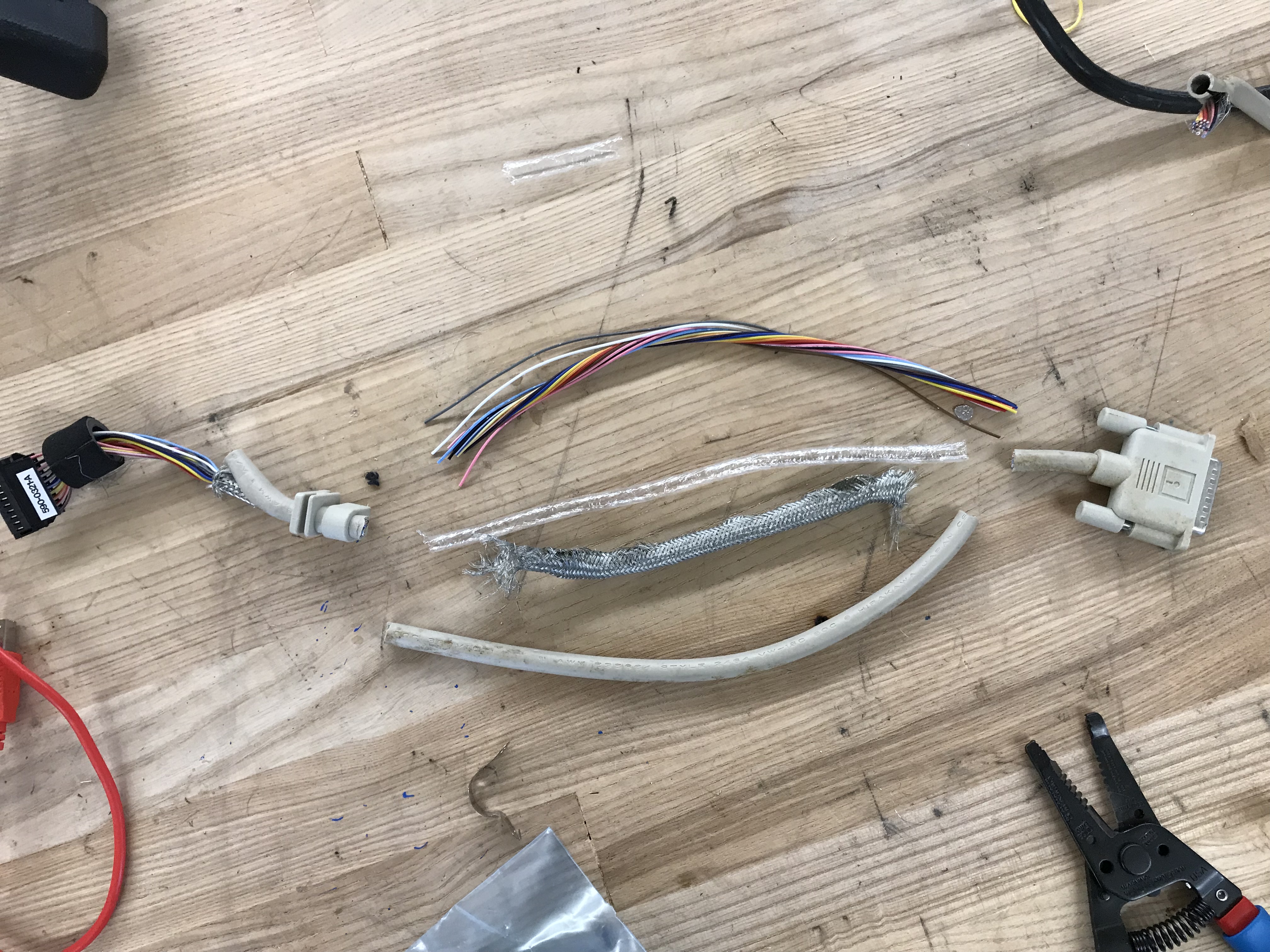
The wire that I am using is from a cable to an old Apple floppy drive which just happened to be the right gauge. I cut all of the
sheathing off and used what was inside.

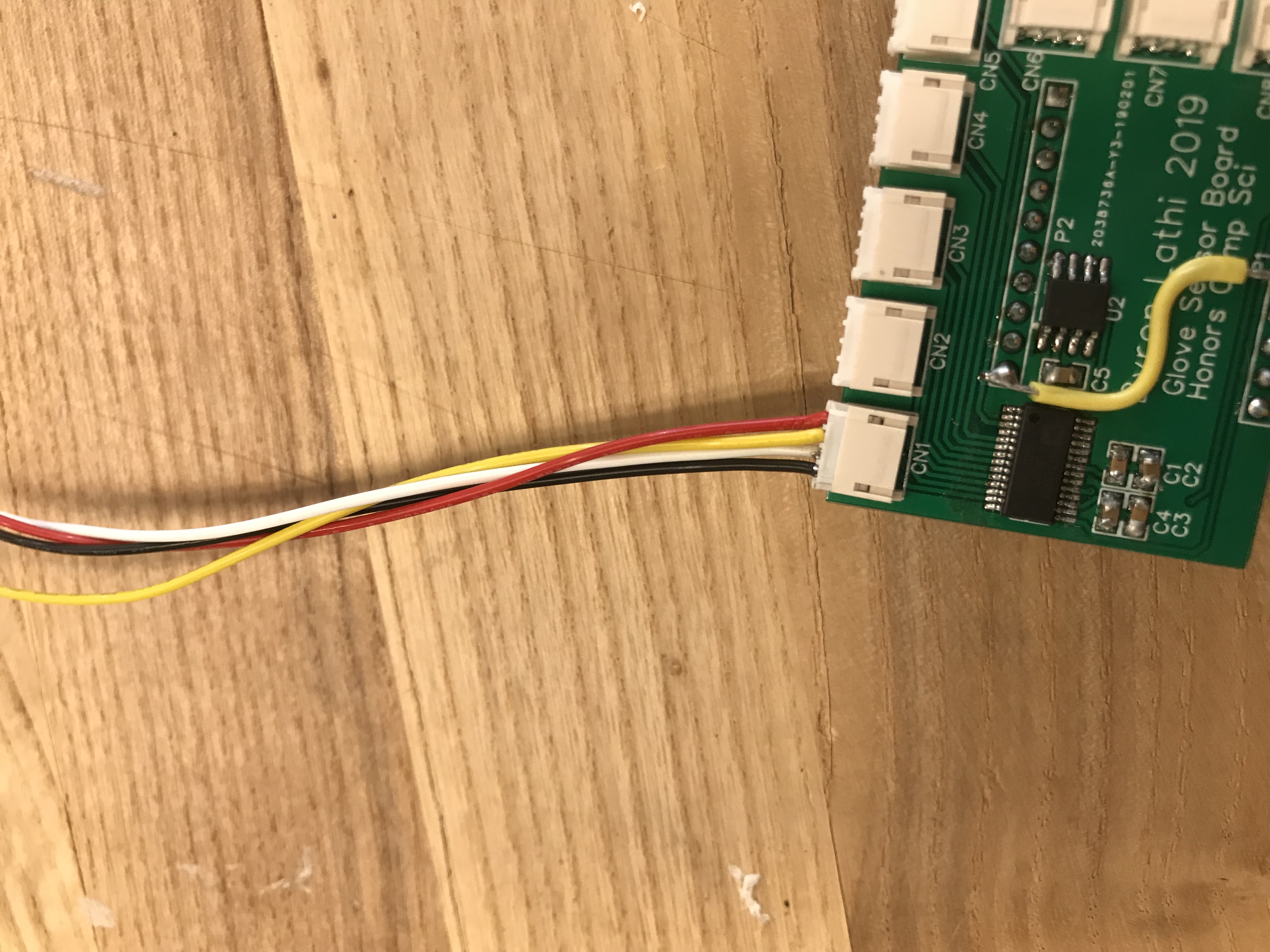
Here is a closer view of the board that shows the connectors. The yellow wire is a bodge since the chip-select pin I was going to use
for SPI was actually reserved for something else. The wire simply goes from one of the GPIO pins on the breakout board back to the
pin that I was going to use.

You can check out some videos of it working below:
Glove Controller Potentiometer Testing
Glove Controller Finger Testing