FPGA Graphics: Part 8
Color bitmap mode was easier than I thought. First I copied and pasted the code from the mono lowres mode, then I copied and pasted the code from the color text mode. The only difference is that it does not use the value as a character, it just writes the value as normal.
The code for the 6502 is similar as well, only much longer. I changed up the test image a little bit to represent the new mode, and I also added color to it. The computer writes by first writing the color value and then writing the data value.
The picture is stored first as a black and white image, followed by color data.
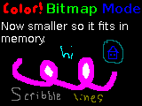
Here is the picture that I started with:

I then used a 8x1 grid to figure out the color information. Because each bit is
a pixel, there can only be 2 colors per byte, a value for a 1 and a value for
a 0. For each box in the grid, I fill out another image with 1 pixel for the
foreground color and 1 pixel for the background color. The colors are the same
as in text mode which I explained in Part 3.
The color data image looks like this:

Right now the color image is done by hand, but the binary is done by a python
script. Once I have the colors that I want, I can desaturate the source image
into black and white, where white uses the foreground color and black uses the
background color. This image looks like this:

Both of those images are converted into binary and are flashed into the ROM.
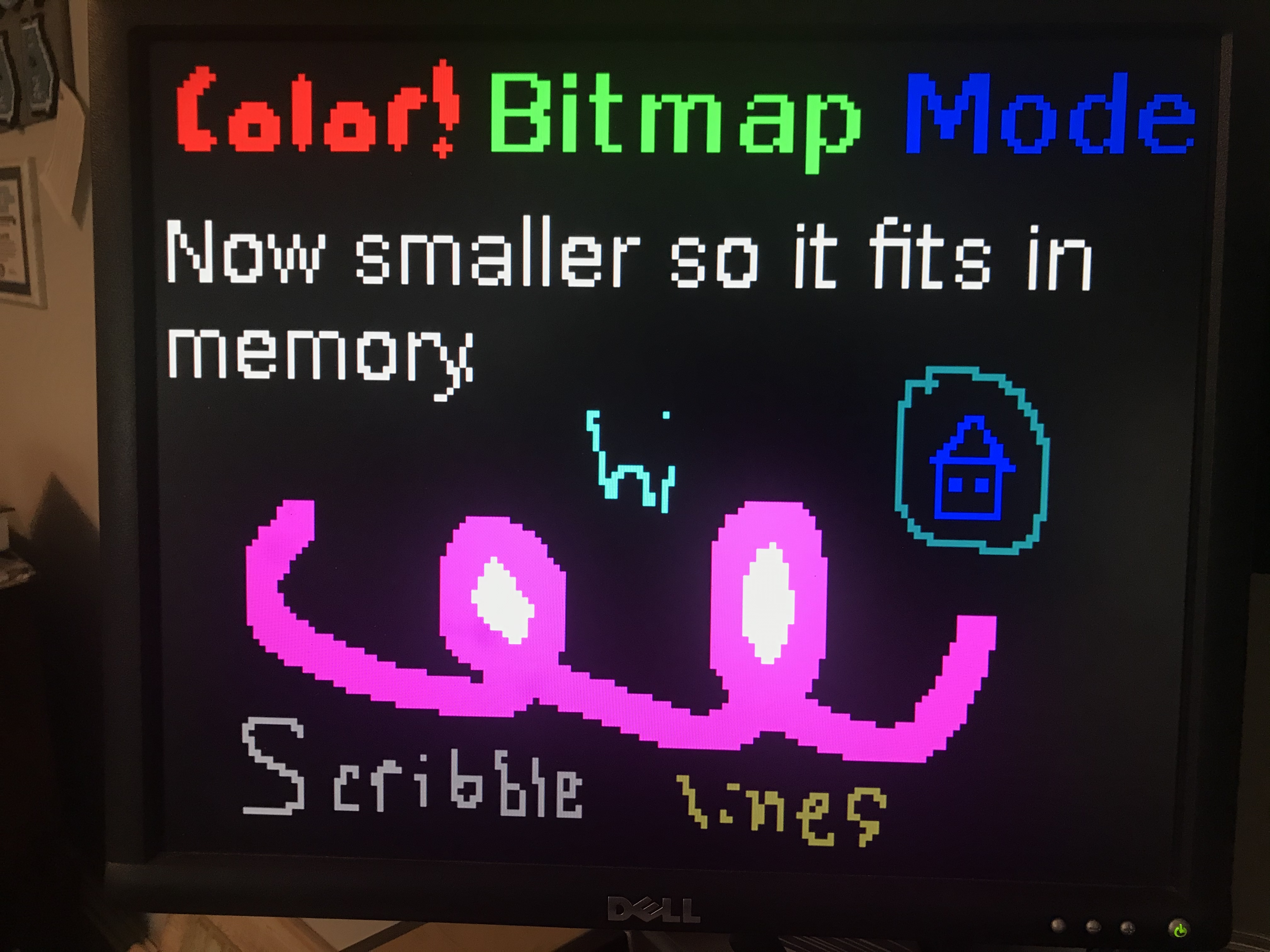
Once on the screen, the image looks like this:
