FPGA Graphics: Part 3
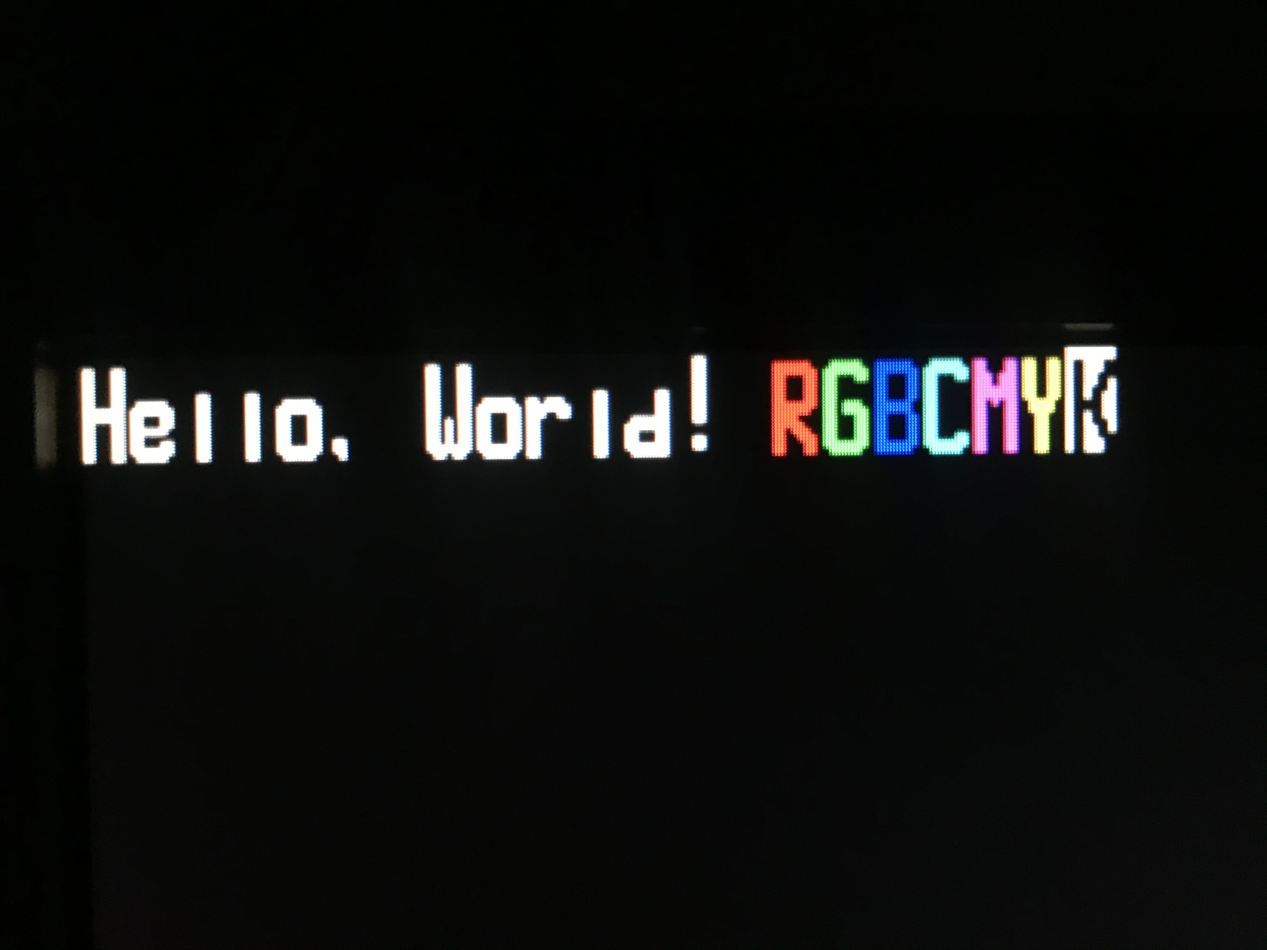
The main focus of this update is color.

The color is implemented as RGBI with 1 bit for each primary color and 1 bit for intensity for the foreground and background, giving you 16 colors for both. Since the VGA on this board is 4 bits per color, the highest bit is always set to the color bit, and the other 3 bits are set to all 1s if both the color and intensity bit are set, otherwise they are 0.
Here’s what the code looks like for that:
assign r_fgnd [3] = colr_val [6];
assign r_fgnd [2:0] = (colr_val [7] & r_fgnd [3]) ? 3'b111 : 3'b000;

assign r_bkgnd [3] = colr_val [2];
assign r_bkgnd [2:0] = (colr_val [3] & r_bkgnd [3]) ? 3'b111 : 3'b000;

assign red_o = pixel ? r_fgnd : r_bkgnd;
The pixel value is created in another module from the current screen location, then the color is applied after. This only shows the red channel but is repeated another 2 times. Both the foreground and background colors are created but only one of them is applied at the end.
Another big change in this update is switching from registers to wires. I realized that many of the problems I was having were from timing, so by replacing a lot of sequential logic with combinational logic I remove that from the equation. The other solution was just to make it run faster. The main clock is at 50MHz, which is only double the pixel clock of 25MHz. This means that board only gets 1 extra clock cycle before it has to output the next pixel which is not enough. I solved this the easy way by making another clock using a PLL at 450 MHz, which is the fastest this chip can do. It probably doesn’t need to be that fast, but it works for now and it doesn’t use too much power anyway.
I also fixed the weird artifacts in the text. They were a result of the 6502 computer constantly writing to the display. Changing the program so that it only wrote once fixed the problem.