FPGA Graphics: Part 1
To start, this project will just have a monochrome text mode. Traditional VGA text mode is 720x400 which isn’t supported on my monitors, so instead I’ll be using 640x480 with 8x16 characters, which means 80x30 text resolution. The reason I am just doing monochrome text is because I would not have enough room in the FPGAs internal RAM to store everything, I would need to use the other RAM on the dev board which I have not done yet.
The program has two memory areas, the screen RAM and the character ROM. The screen RAM holds ascii codes which then get translated into addresses in the character ROM. Each character has 16 bytes, one for each line of the character. Right now you have to use the debug tools to directly edit the FPGA memory but later you would use the address and data lines from the 6502 to change them.
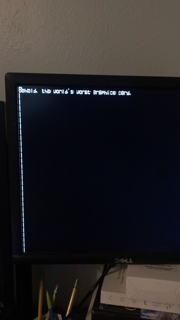
Here is the first time I plugged it in:
It’s trying to do something, but all the characters are boxes and they’re not supposed to be scrolling down the screen like that. I fixed the problem with the characters which gave me this:
I’m not sure why the positioning is wrong but it’s easy enough to change on that monitor. Next I fixed the scrolling problem.
The characters all look weird and that is because the first pixel of each character is each actually the first pixel of the previous character. What happens is it changes the address to look at and tries to read from the ROM at the same time, which means the first time it reads it actually reads from the previous location, but the next seven times it reads from the correct location. I still haven’t fixed this but what I did was move all of the characters over 1 bit. They were all 7 bits wide to leave space between the characters, so now the space is before instead of after. I still haven’t fixed that and I don’t think I will. If you are making a game or something you could still make 8 bit wide characters if you want, you’d just have to have the first bit in the previous character.
The next problem I am left with is this color issue where if the last bit of a line is set, it turns red to the left and blue to the right, like this.
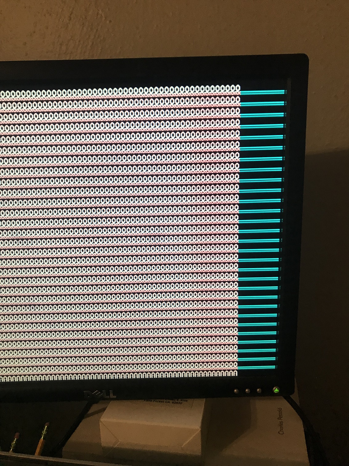
I think this was just an issue with timing so I changed how the VGA signals were set. Before, they were registers which were set at every clock pulse. Now, they are wires which are set based on the pixel value and the current horizontal position. If it’s inside the drawing area, then every VGA bit is set to the pixel value, if not then it’s zero. This way there doesn’t need to be a clock pulse to set the output. This appears to have fixed it. That wasn’t that last problem though, now I am left with this:
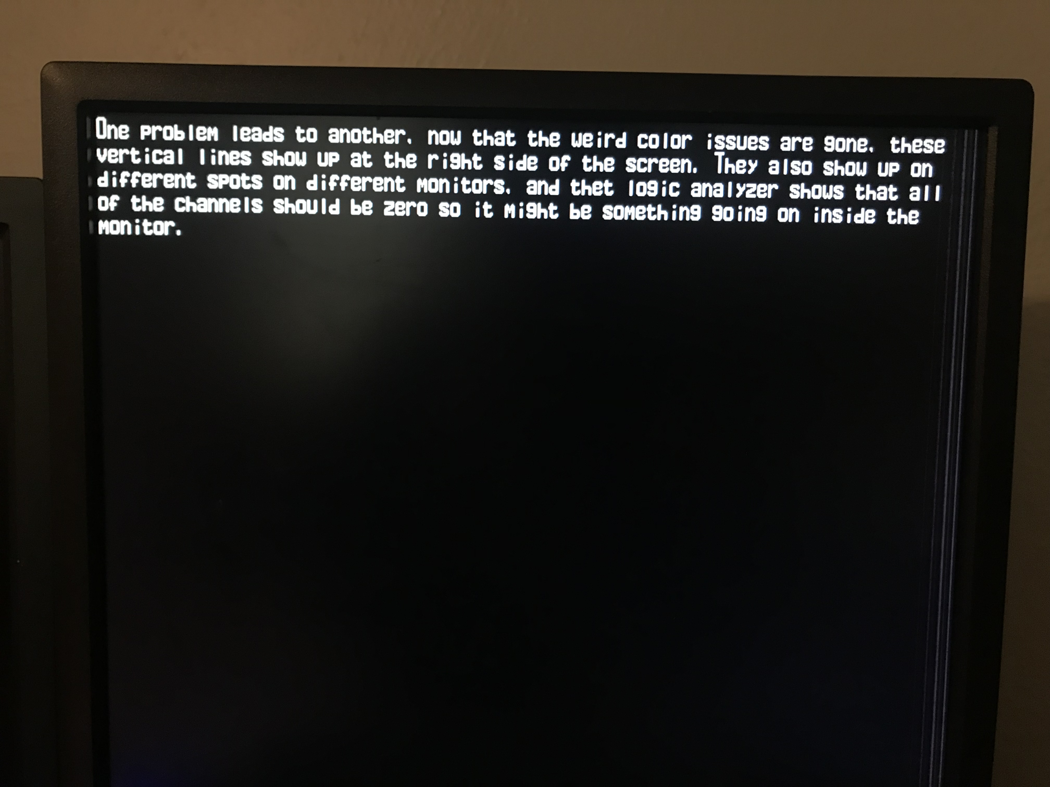
This one still confuses me because the lines at the end show up in different places on different monitors, and when I look at the logic analyzer, none of the VGA bits are on so there shouldn’t be anything on.
Overall, this is a good start and what I need to do next is find a way to edit the screen ram while drawing. I tried to do this earlier with the the switches built in but I couldn’t get it to work so I took them off. I’ll figure it out eventually though.
All of the code is on my GitLab.