Adding a Keyboard
The keyboard that I chose to add was from an old Apple IIc that a friend gave me. It’s a pretty bad keyboard but if I ever want to replace it with the good Alps one, it’ll be plug and play. Originally I wanted to use a generic Logitech membrane keyboard but the custom PCB that I ordered doesn’t look like it will be getting here anytime soon due to the current pandemic.
Since I had the Apple IIc, I salvaged the keyboard, the keyboard encoder, and the keyboard ROM. The keyboard is a simple matrix style keyboard but caps lock, shift, and control are separate. The keyboard encoder is the 9600PRO which I could not find much information on, other than this one datasheet. It takes in the keyboard matrix, shift, and control lines and outputs a 9 bit value for what key combination is pressed. This is used as the address for the ROM which then outputs the correct 8 bit character or control character. Since I used the Apple ROM, it was all wired up exactly the same as it was in the original computer, using this schematic.
A few things had to be changed though. The encoder has 2 main output signals, Any Key Down and Data Ready. Any Key Down, or AKO, is high if there is a key pressed down. Data Ready is a pulse whenever the encoder is finished figuring out which key combination is pressed.
For my first try, I checked to see if AKO was high and then immediately got the data from the ROM. All of the data lagged behind by one keystroke though, because the AKO output is set before the encoder is done. I can’t just wait for Data Ready though, because I might miss the pulse. What I did to solve this was use an SR latch which is set by Data Ready and can be reset by the VIA. When you call getkey, the CPU constantly checks to see if Q goes high. Once it does, it can read the value from the ROM.
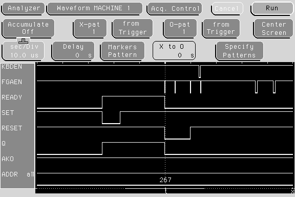
Here is a screenshot showing this sequence:

Set is the inverted Data Ready signal, since the NAND SR latch uses inverted inputs. READY and Q are both the output from the latch. AKO is high for the whole time, but only because it is set a while before the data is ready. KBDEN is the select signal for the keyboard ROM, and FGAEN is the select signal for the graphics. Once set falls, READY goes high until the CPU detects it and resets it. It then reads the ROM and writes that to the screen. You might notice in between READY falling and KBDEN falling FGAEN falls a few times. This is because the CPU address lines don’t all get set at the exact same time. This caused a problem because the inputs to the FPGA were clocked at 50MHz, which could detect these glitches. I changed it so they were clocked at 1MHz, as is expected by all 6502 peripherals, and that fixed the problem. ADDRESS is the address of the character in the ROM, x267 goes to a ‘g’, using the 342-0132-D ROM.