Adding an LCD
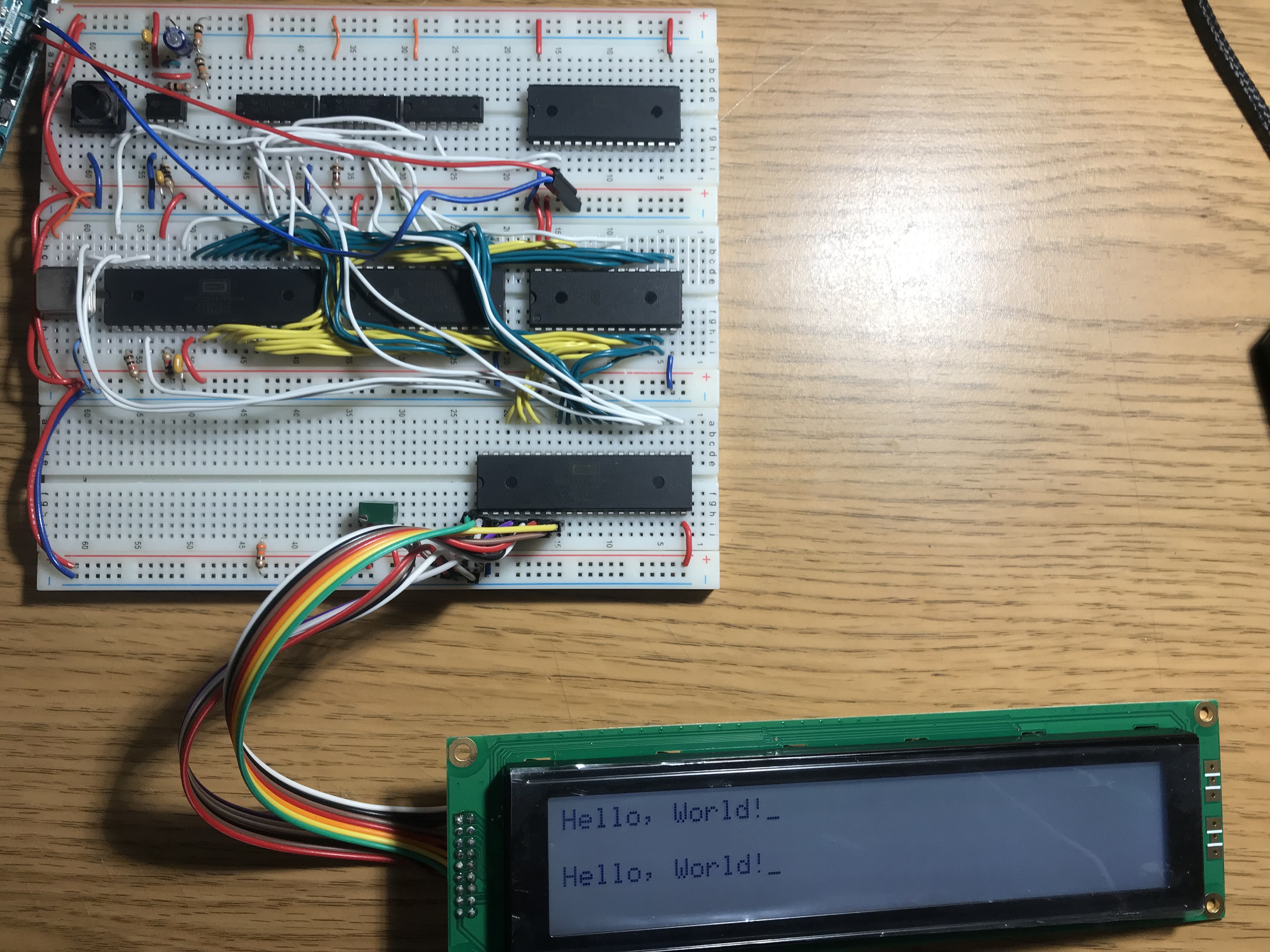
Here is the LCD connected to the computer:

I ended up connecting the LCD to the VIA instead of directly to the CPU bus so I didn’t have to mess with any address decoding, so the circuit is the exact same as last time just with the LCD on port A instead of some LEDs. Ideally I would still want some IO lines left over after adding the keyboard though, so either the display will have to be accessed directly or I’ll have to get 2 more VIAs. Each VIA only takes up 16 bytes of memory, so it’s not a huge impact there.
Most character LCDs are interfaced in the exact same way, and this one is no different, other than it acts like two 2x40 displays instead of one 4x40, which is why so see the text repeated on the top and bottom. There are 12 control lines, except I’m using 4 bit mode, and I’m never going to read from the display, so that drops it down to 7 lines. Normal displays would have 6, but since this is two displays there are two enable lines.
The datasheet doesn’t give too much information other than an example C program, but this explains more clearly what you have to do to get the display in the correct mode.
Since these new programs are much longer, I wrote a few basic tools to help. The first is a batch file which assembles and links the source file. The next is a python program which takes the raw binary output from the linker and turns it into an array that I can copy and paste into the arduino program which runs my EEPROM programmer. It’s still a work in progress but it’s much easier than copying it over one byte at a time. Ideally I would be able to upload the binary file to the arudino over USB without having to change the program.