IO for the 6502
The CPU can’t do much on it’s own, it can only talk to other things. So far I’ve just been looking at what its saying, but now it has a way to control other things directly.
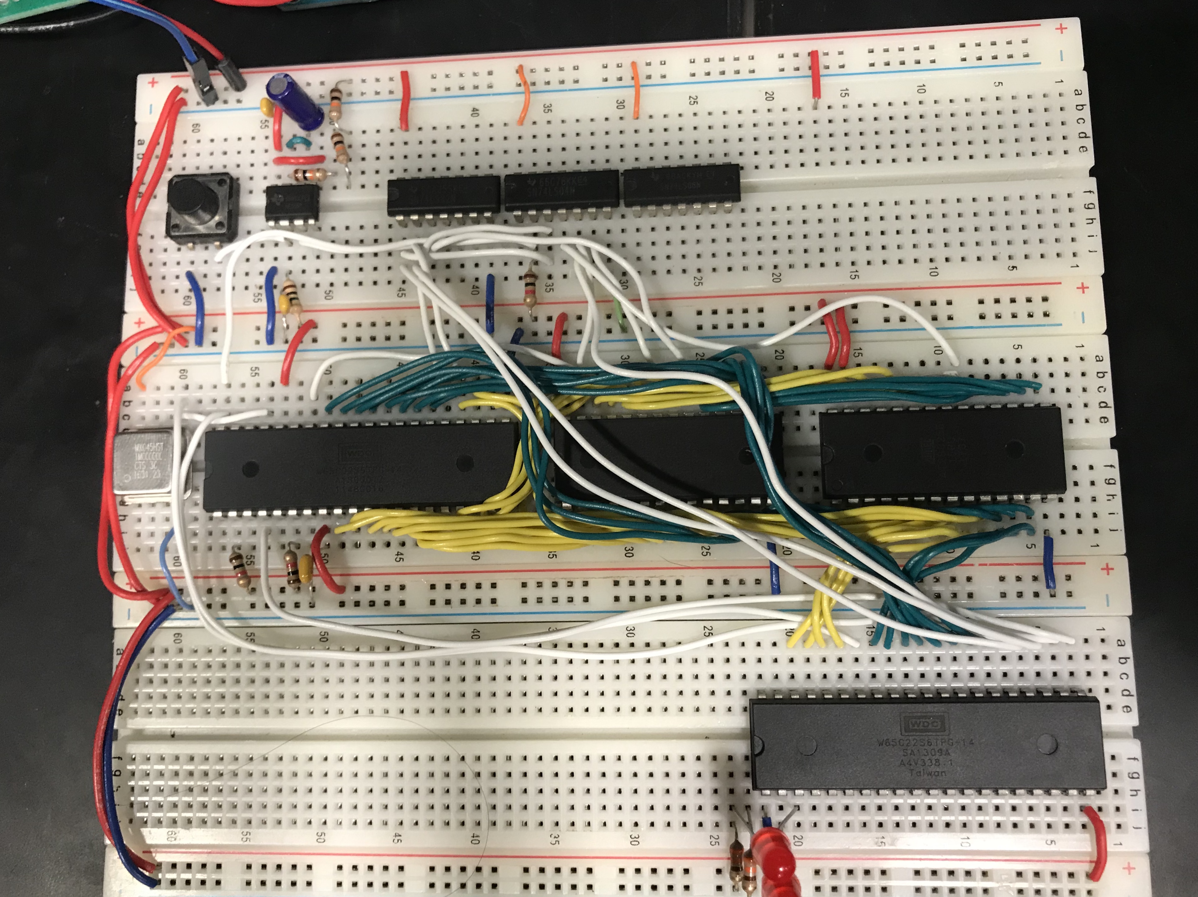
The 6522, called the VIA, is a chip that lets you control 16 IO bits, as well as timers, counters, and interrupts. You write to it just like you would write to memory. In this case, it’s wired up so that its address is $4000. Normally you wouldn’t have it taking up 16Kb, since there are only 16 bytes to write too, but it’s easier this way since I don’t need much RAM anyway.
Here is the updated circuit:

Here is a short testing program that flashes some LEDS:
start:	lda #$ff
	sta $4003	; Set DDRA to all output
loop:	lda #$01
	sta $4001	; Set Port A to 01
	jsr delay	; Wait
	lda #$02
	sta $4001	; Set Port A to 10
	jsr delay	; Wait
	jmp loop 	; Go back to beginning

delay:	ldy $ff		; set y to 255
delay1:	ldx $ff		; set x to 255
delay2:	dex		; decrement x until 0
	beq delay3	; go to delay3 when x=0
	jmp delay2
delay3:	dey		; decrement y, then run x from 255 to 0 again
	beq delay4	; after going from 255-0 256 times, delay is over
	jmp delay1
delay4: rts ; Go back to the main programThis alternates two LEDs attached to pins PA0 and PA1 of the VIA. There is no simple “delayms()” in assembly, so the delay program that I have counts from 255 down to 0 256 times, it ends up flashing about 5 times a second. You can do math and count how many cycles each of those instructions will take to find the exact time if you want to.
To read inputs with the VIA, you set the data direction to 0 for that bit, and then you can read the value from the same register you write to. I attached some buttons to pins 3 and 4 and used the following program to turn on and off the LEDs:
start:	lda #$03
	sta $4003	; Set pins 1 and 2 to output, the rest are inputs
loop:	lda $4001	; Get current values
	lsr		; shift right twice
	lsr		; so bits 2 and 3 become 0 and 1
	sta $4001
jmp loop ; Go back to beginningLocation $4001, called ORA/IRA is both the input and output register, depending on if you are reading or writing.
Next step is to add a screen. I have a big 40x4 character LCD, but I want to save that for later since it’s a little more complex. I do have a smaller 16x2 LCD, but it’s made for 3.3v, not 5 so I can’t use it.
I also have a 6551 ACIA, which would let me talk to the computer over serial. That will have to wait until a little later until I am more comfortable with assembly.